
Projects

What Is a Coding Switch and How Does It Work?

A Coding Switch is a small hardware device that converts a physical selection into an electrical code. It may look like a rotary dial, DIP switch, or compact panel selector. Inside, metal contacts open and close as the switch moves. Each position represents a value, such as 0, 1, 5, or 9.

David A. Patterson, a respected computer architecture expert, often emphasizes the design principle, “Make the common case fast.” That idea also explains a practical Coding Switch. The device gives a controller a simple, quick signal instead of requiring complex mechanical interpretation. In a rotary version, several contacts may create binary, BCD, or Gray-code outputs. A microcontroller then reads those lines through digital input pins. Pull-up resistors keep the signal stable. Software interprets the selected pattern.

The process sounds simple. It is not always clean. Contact bounce can create several rapid signals during one turn. Wiring mistakes can also produce an invalid code. Engineers therefore add debounce logic, filtering, or a lookup table. The switch must also match the voltage and current limits of the circuit.

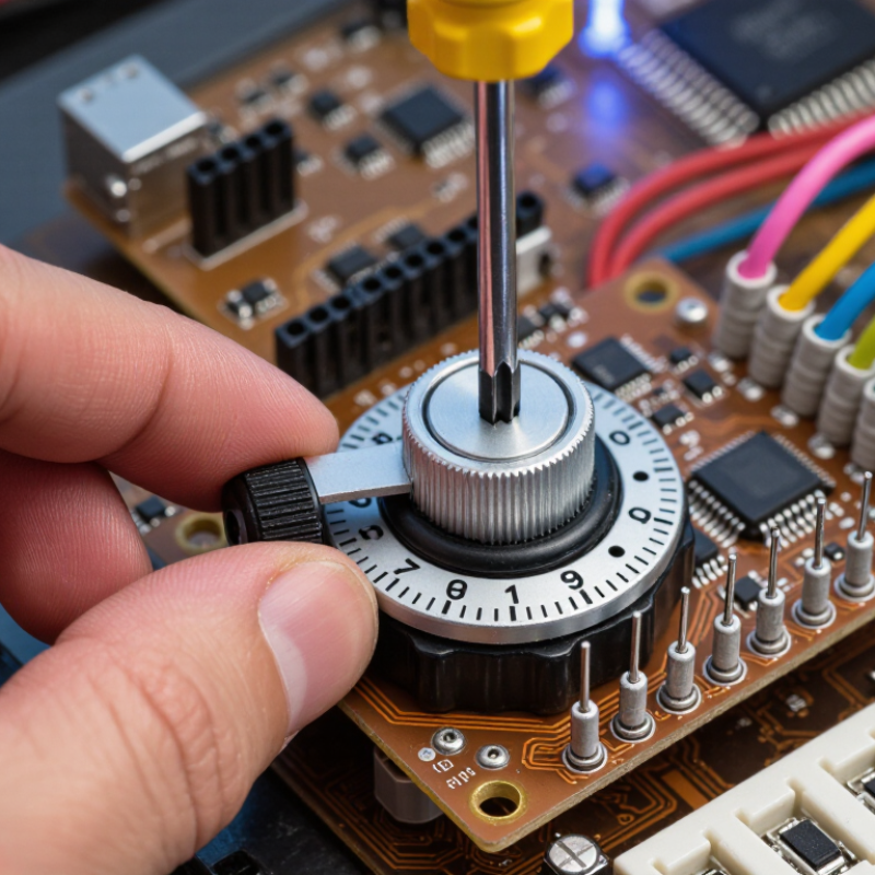
In real equipment, you might turn the dial with a screwdriver, hear a faint click, and see a controller change its operating mode. That physical detail matters. A Coding Switch connects human choice with machine-readable data.

The term can vary across industries. Some manufacturers use it for coded rotary selectors, while others describe programmable switch assemblies differently. Checking the datasheet remains essential. A clear explanation should admit that limitation.
What Is a Coding Switch and How Does It Work?

Definition and Purpose of a Coding Switch

What Is a Coding Switch and How Does It Work?

Definition and Purpose of a Coding Switch

A coding switch is a compact control device that assigns a fixed code to equipment. It commonly uses rotary positions, slide tabs, or small push mechanisms. Each position changes an electrical contact pattern. The controller reads that pattern as a number, address, mode, or operating limit.

Its purpose is simple: configure hardware without rewriting software. A technician might set a conveyor address to 07. Another switch may select speed, sensor type, or communication settings. Binary switches use on/off combinations, while rotary versions often show decimal values directly. The setting remains visible and usually survives power loss. That practical detail matters on factory floors.

Industrial equipment increasingly needs this kind of clear identification. The World Robotics 2024 report recorded 541,302 industrial robots installed worldwide during 2023. It also reported more than 4.2 million robots operating globally. More connected machines create more configuration points, although a coding switch is not a complete control system.

The device does not encrypt information. It only represents a setting. That distinction is easy to miss. Incorrect positions can create address conflicts, unexpected machine behavior, or service delays. Dust, vibration, and worn contacts can also cause reading errors. NIST’s SP 800-82 guidance treats industrial control environments as systems requiring careful configuration and change management. A technician should record every switch position, verify the controller’s interpretation, and question whether a manual setting still suits the equipment.

Key Components and Operating Principles

What Is a Coding Switch and How Does It Work?

A coding switch is a compact input device that converts a physical position into an electrical code. It often uses a rotary dial, sliding contact, or grouped terminals. Inside, conductive contacts touch selected paths as the actuator moves. Each position represents a value, such as a digit, setting, or binary pattern. The housing holds the mechanism firmly and protects it from dust and accidental contact.

The key components include the actuator, contact array, terminal pins, detent mechanism, and insulating body. The actuator selects a contact pattern. The detent mechanism provides small clicks and helps prevent accidental movement. Terminals carry the coded signals to a controller or circuit board. Many designs use pull-up or pull-down resistors, so an open contact still produces a readable logic level. Simple wiring. Reliable interpretation.

Operation depends on controlled continuity. When the dial reaches a position, specific terminals connect or disconnect. The controller reads this pattern and converts it into usable data. Mechanical contacts can bounce briefly, causing unstable readings. Software or hardware debouncing usually corrects this issue. In practical testing, a multimeter can confirm each position before installation. Do not assume every code sequence is intuitive. I have found that unclear labeling creates more errors than the switch itself. Contact wear, poor soldering, and forceful turning can also change performance over time. Testing under real vibration would be wiser, although it is often overlooked.

What Is a Coding Switch and How Does It Work?

A coding switch converts a mechanical position into a defined binary output. This chart shows the ideal output sequence of a generic 2-bit rotary coding switch using Gray code, where only one output bit changes between adjacent positions.

Key Components and Operating Principles

The actuator selects a position, internal contacts connect the common terminal to selected code terminals, and external pull-up or pull-down resistors define the digital HIGH and LOW levels. In the example, the four positions produce 00, 01, 11, and 10. The Gray-code sequence reduces the chance of reading an invalid intermediate value during mechanical movement. Real switches may require debouncing because contacts can briefly open and close several times before settling.

How a Coding Switch Processes Signals Step by Step

What Is a Coding Switch and How Does It Work?

How a Coding Switch Processes Signals Step by Step

A coding switch is an electronic control device that converts a selected input into a defined digital code. Its exact meaning can vary across engineering fields. In practical systems, it may read a rotary position, button state, or sensor level. The switch then sends coded information to a controller.

The process begins when an input signal reaches the switch. A conditioning circuit removes minor voltage noise and shapes the signal. Mechanical contacts may also need debouncing, because they can open and close several times within milliseconds. The circuit then samples the cleaned signal at a set interval. Timing matters here. A poorly chosen sampling rate can miss a fast change.

Next, the logic section compares the signal with programmed thresholds. It assigns a binary value, such as 0 or 1, to each valid condition. Several inputs can form a larger code, such as 0101. Error-checking logic may reject unclear combinations or impossible states. This step improves reliability, but it cannot repair every wiring fault.

The final coded signal travels through an output interface to a control unit. The receiving unit interprets the code and triggers an action, such as changing speed or selecting a mode. In field testing, an oscilloscope can reveal delays, bouncing, or unstable levels. I have found that diagrams often look cleaner than real signals. Temperature, cable length, and grounding can still alter performance.

Common Types and Applications of Coding Switches

What Is a Coding Switch and How Does It Work?

A coding switch is a compact input device that selects or represents a specific value. Inside, contacts change position when a knob, slider, or button moves. The connected controller then reads that position as a digital code. This simple action helps equipment identify settings without a full keyboard or complex interface.

Common types include DIP switches, rotary coding switches, thumbwheel switches, and selector switches. DIP switches suit fixed configuration tasks, such as setting addresses on control boards. Rotary types allow users to choose numbered values, often in timers, sensors, and industrial controllers. Thumbwheel switches provide quick manual adjustment in test equipment and older control panels. Selector switches are useful when operators need clear choices between operating modes. Their reliability depends on contact quality, vibration resistance, and correct electrical ratings.

Tips: Match the switch code with the controller’s input method. Check voltage, current, panel space, and environmental exposure before installation. Label each position clearly. A small mistake in binary settings can create a confusing fault. In practice, technicians should test every position instead of trusting the printed scale alone. That detail is easy to miss. Also, mechanical wear may change contact performance over time, especially in dusty or frequently adjusted equipment. No coding switch is perfect. The best choice balances speed, safety, readability, and maintenance needs.

What Is a Coding Switch and How Does It Work? - Common Types and Applications of Coding Switches

Coding Switch Type How It Works Typical Coding Capacity Output or Contact Arrangement Common Applications Key Advantages Important Limitations
DIP Coding Switch Individual slide, rocker, or piano-style sections are set to open or closed positions. Each section represents one binary bit. 2n states; for example, 8 positions provide 256 binary combinations. Usually a set of independent single-pole contacts that are read as a binary code by a circuit. Address selection, configuration settings, operating-mode selection, and equipment identification. Low cost, easy to understand, and suitable for infrequent manual settings. Not ideal for frequent adjustment; switch positions may be difficult to read in confined spaces.
Rotary Coded Switch A knob rotates a common contact across several fixed positions. Internal contacts connect the selected position to an output pattern. Commonly 10 positions for decimal selection; some versions provide 16 positions for hexadecimal coding. May provide one-of-n selection or a coded output such as binary-coded decimal or hexadecimal. Device addresses, channel selection, timing presets, control-panel settings, and measurement-range selection. Fast visual adjustment and clear indexed positions. Requires panel space for the knob and may have limited resolution compared with electronic controls.
Thumbwheel Coding Switch A numbered wheel is turned with a finger or tool. Each wheel generally represents one decimal digit or a coded position. Usually 10 states per wheel; multiple wheels create multi-digit settings. Mechanical contacts or electronic sensing elements generate a digit-based output. Preset values, test equipment settings, industrial controllers, and numerical identification fields. Good numeric visibility and convenient field adjustment. Can be larger and more expensive than a simple DIP switch when many digits are required.
Coded Pushbutton Switch Pressing one or more buttons closes designated contacts or enters a selected code into an electrical control circuit. Depends on the number of buttons and allowed key combinations. Momentary or maintained contacts; a controller may scan the buttons and interpret the code. Access-control keypads, operator interfaces, function selection, and equipment test panels. Intuitive user input and easy code changes without opening the enclosure. Mechanical contacts can wear, bounce, or require protection from dirt and moisture.
Slide Coding Switch A slider moves between marked positions to open or close contacts and establish a predefined electrical configuration. Typically 2 states per section; multi-section assemblies provide multiple binary combinations. Usually independent single-pole contacts, with the selected state read directly by hardware or software. Compact electronic devices, communication equipment, configuration panels, and power-management settings. Compact construction and relatively simple operation. Small sliders may be hard to operate and may be changed accidentally without a protective cover.
Coded Selector Switch A rotary actuator selects one of several positions, and the switch routes a common electrical path to the selected circuit. Usually one active position at a time; capacity equals the number of indexed positions. One-of-n switching, sometimes with multiple poles for switching several circuits simultaneously. Operating-mode selection, motor-control settings, instrumentation, and source or range selection. Provides positive position selection and can handle more than one circuit with multi-pole designs. The selected position may not directly represent a binary value and may require additional circuitry for digital processing.
Electronic Coding Switch A sensor, membrane interface, or electronic input detects the selected code and sends it to a logic circuit or microcontroller. Determined by the input matrix, sensing resolution, and control logic. Digital signals, scanned key matrices, encoded serial data, or logic-level outputs. Automated equipment, embedded systems, touch interfaces, smart instruments, and programmable controls. Flexible, highly configurable, and suitable for frequent input or remote processing. Needs power and control electronics; software errors, electromagnetic interference, or sensor failure may affect operation.
How coding switches work: The selected mechanical or electronic position creates a defined electrical state. A circuit, controller, or software system then interprets that state as a binary value, decimal digit, hexadecimal value, or one-of-n selection.

Advantages, Limitations, and Selection Considerations

A coding switch is a small electromechanical input device that represents settings through numbered, binary, or hexadecimal positions. A rotary type uses a dial, while a DIP type uses several tiny on-off levers. Each position changes electrical contacts, allowing a controller to read an address, operating mode, or device ID. With four binary switches, the theoretical range is 16 combinations. The circuit still needs pull-up or pull-down resistors, filtering, and software validation.

The main advantage is practical simplicity. Technicians can change settings without connecting a laptop or rewriting firmware. The International Federation of Robotics reported 541,302 industrial robots installed worldwide in 2023. That expanding equipment base increases demand for clear, field-adjustable configuration methods. Coding switches also consume little power and remain readable during maintenance.

They are not perfect. Small switches can be misread, contacts may wear, and vibration can cause uncertain readings. A wrong position may remain unnoticed for months. That is the uncomfortable part.

Selection should begin with the environment, not appearance. Check contact rating, operating temperature, shock resistance, sealing, and expected switching cycles. For frequent adjustments, a rotary encoder may provide better feedback than a recessed DIP switch. For safety-related controls, independent verification and fault detection are essential. IEC 60512 testing methods can help evaluate connector and contact performance, but they do not replace application testing.

Consider the required code system carefully. Binary is compact, while Gray coding can reduce transition errors. Labels, tactile feedback, and access clearance matter too. Engineers often underestimate maintenance time. That mistake deserves a second review.