Projects

What Is Steel Fabrication and How Does It Work?

Steel fabrication turns engineered steel into usable structures, components, and assemblies. The work may involve cutting, bending, drilling, welding, bolting, and protective coating. Each step affects the final result.

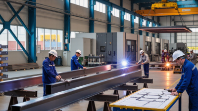
A fabricator may begin with structural drawings, digital models, and a material schedule. Steel plates or sections then move through saws, plasma cutters, press brakes, and welding stations. Measurements matter. A two-millimeter error can complicate assembly later.

Duane K. Miller, a recognized welding engineer and industry educator, has emphasized, “Welding is a fabrication process, not merely a joining process.” His point is important. Welding changes dimensions, creates heat effects, and demands controlled procedures. It is not simply fastening two pieces together.

Reliable steel fabrication depends on more than skilled hands. It requires material traceability, qualified welders, calibrated equipment, inspection records, and careful interpretation of design requirements. Experienced teams check joint preparation, weld size, surface condition, and dimensional tolerances before shipment.

The workshop can feel highly controlled. It is not perfect.

Steel may distort during welding. Coatings may fail when surfaces are poorly prepared. Drawings may also leave room for interpretation. These issues require practical judgment, not blind confidence.

This guide explains how steel fabrication works, from design review to finished delivery. It also examines common equipment, quality checks, safety considerations, and project risks. Readers will see why accurate planning matters before steel reaches the shop floor. The process is technical, physical, and sometimes surprisingly unforgiving.
What Is Steel Fabrication and How Does It Work?

Steel Fabrication Defined: Processes, Materials, and ASTM A36’s 36 ksi Yield Strength

Steel fabrication turns flat plate, bar, and structural sections into usable components through controlled cutting, forming, joining, and finishing. Fabricators may use sawing, shearing, plasma cutting, drilling, bending, and welding. Each operation changes the steel’s geometry or surface condition.

ASTM A36 remains a common reference for carbon structural steel. Its specified minimum yield strength is 36 ksi, or approximately 250 MPa. The material typically has a tensile strength range of 58–80 ksi, depending on product form and thickness. Those values matter during design and inspection. A beam that looks strong may still fail if its measured properties, weld quality, or dimensions fall outside requirements.

The World Steel Association’s World Steel in Figures 2024 reported about 1.892 billion tonnes of crude steel production in 2023. That scale shows why consistent fabrication controls are essential. In a working shop, technicians verify heat numbers, review mill certificates, check cut edges, and inspect welds visually or with nondestructive testing. Small distortions can become expensive during erection. Fabrication is not perfectly predictable. Heat input, residual stress, and operator judgment can alter the final result. ASTM A36 also should not be treated as a universal solution; engineers must confirm thickness, loading, corrosion exposure, and connection details before approval.

Engineering Steel Components: Design Loads, AISC 360 Standards, and Millimetre Accuracy

Steel fabrication turns engineered drawings into accurate, load-bearing components. The process begins with design loads, including dead, live, wind, seismic, and connection forces. Engineers use these values to size beams, plates, braces, and welds safely.

AISC 360 provides widely accepted requirements for structural steel design and fabrication. It guides material selection, member strength, connections, welding, bolting, and inspection. Fabricators translate approved drawings into cutting lists, CNC files, fit-up plans, and shop weld procedures. Millimetre accuracy matters here. A small hole offset can create serious alignment problems during erection. Measurements should be checked after cutting, drilling, assembly, and final inspection. Digital tools improve control, but they do not replace judgment. Real steel can distort from heat, restraint, or uneven handling. That is where experience becomes important.

Tips: Confirm design loads before detailing connections. Show weld sizes clearly. Record actual dimensions, not assumed ones. Leave practical access for tools and inspection.

A useful workflow includes trial assembly for complex frames. Technicians can identify clashes before transport reaches the site. However, not every mismatch indicates fabrication failure; site surveys may reveal inaccurate reference points. Engineers, inspectors, and fabricators should review discrepancies together. Clear revision control prevents an outdated drawing from entering production. The best result is not merely a clean-looking frame. It is a component that matches the approved design, tolerances, inspection records, and real construction conditions.

Cutting and Forming Steel: CNC Tolerances, Plate Thickness, and Section Profiles

Steel fabrication turns flat plate, bars, and structural sections into accurate working components. World Steel Association data recorded about 1.89 billion tonnes of crude steel production in 2023, showing the scale of this essential material. Yet steel quality depends on more than volume. Cutting begins with saws, lasers, plasma, or waterjet systems. Each method creates different heat effects, edge conditions, and practical tolerances.

CNC equipment can cut complex shapes repeatedly, but “CNC accuracy” is not one fixed number. Tolerance depends on material grade, thickness, machine condition, programming, and thermal distortion. ISO 2768-1, for example, gives general linear tolerances such as ±0.3 mm for 30–120 mm dimensions under its medium class. Critical holes may need a tighter, specifically stated tolerance. A neat drawing can still fail if the tolerance is missing.

Plate thickness also changes fabrication behavior. Thin plate bends quickly and may distort from welding heat. Thick plate needs greater cutting energy, edge preparation, and sometimes preheating. ASTM A6/A6M defines dimensional tolerances for many steel products, but the allowed variation depends on the ordered thickness and product type. Section profiles create different problems. I-sections carry loads efficiently, channels suit edge framing, and angles simplify connections. Forming introduces springback, so the final angle may not match the press setting exactly. This is where shop measurements matter. The first part should be checked carefully, even when the model looks perfect.

What Is Steel Fabrication and How Does It Work? - Cutting and Forming Steel: CNC Tolerances, Plate Thickness, and Section Profiles
Fabrication Operation Typical Steel Form Common Working Thickness or Size Typical Dimensional Capability How the Process Works Important Design Considerations
CNC Fiber Laser Cutting Carbon-steel sheet and plate; stainless and other alloys may require different settings Approximately 0.5–25 mm for many general fabrication applications Typical cut-position tolerance: about ±0.10–±0.30 mm, depending on material, thickness, machine, and part size A focused laser beam melts or vaporizes the material while an assist gas removes molten metal from the cut zone. Small holes, narrow slots, heat-affected zones, and thermal distortion should be reviewed during design. Actual tolerance must be confirmed with the fabricator.
CNC Plasma Cutting Carbon-steel, stainless-steel, and aluminum plate Approximately 1–50 mm; high-definition systems can cover selected thicker ranges Typical cut-position tolerance: about ±0.50–±1.50 mm An electric arc creates a high-temperature plasma jet that melts the steel and blows the molten material away. Cut quality is influenced by amperage, torch height, travel speed, plate flatness, and the condition of the consumables. Edge angularity may increase on thicker plate.
CNC Oxy-Fuel Cutting Primarily carbon-steel plate Approximately 6–300 mm, depending on equipment and grade Typical cut-position tolerance: about ±1.00–±3.00 mm The steel is preheated and then oxidized by a high-velocity oxygen jet, which removes the resulting iron oxide. It is well suited to thick carbon-steel plate but produces a larger heat-affected zone than many cold-cutting methods. Machining may be needed for close-fit interfaces.
CNC Waterjet Cutting Carbon steel, stainless steel, aluminum, and mixed-material assemblies Approximately 1–150 mm; practical limits depend on pump power and part geometry Typical cut-position tolerance: about ±0.10–±0.30 mm; tighter results require controlled process conditions A high-pressure water stream, often containing abrasive particles, erodes the material without a significant heat-affected zone. Useful for heat-sensitive materials and laminated parts. Cutting speed is generally lower than laser or plasma, especially on thick plate.
Press-Brake Forming Sheet and plate, commonly supplied as flat blanks Approximately 0.8–25 mm in general fabrication; capacity depends on press force and bend length Typical bend-angle tolerance: about ±0.5° to ±1.0°; linear bend dimensions often fall near ±0.25–±0.50 mm under controlled conditions A punch forces the blank into or against a die to create V-bends, channels, offsets, and other profiles. Inside radius, springback, grain direction, tooling, bend allowance, and minimum flange length affect the finished dimensions. A bend deduction should be included in flat-pattern calculations.
Roll Forming or Plate Rolling Long sheet, strip, and plate sections Sheet and plate from approximately 1–20 mm for many fabrication projects Typical formed-radius tolerance: approximately ±1–3% of the specified radius, subject to material and machine capability Material passes through successive rollers that gradually produce a constant radius or continuous structural profile. Springback, edge wave, plate flatness, rolling direction, and the required tangent length must be considered. Trial forming may be required for critical radii.
Structural Section Cutting and Drilling Angles, channels, I-sections, hollow structural sections, and flat bars Common section depths: approximately 50–600 mm; actual availability varies by standard and region Typical cut-length tolerance: about ±1–±3 mm; hole-position tolerance commonly requires a separate drawing specification Sections are cut to length and may be drilled, punched, coped, notched, or prepared for welding and bolting. Specify section designation, grade, cut orientation, hole diameter, edge distance, cope geometry, and weld-access requirements. Rolled-section dimensions can vary within the applicable product standard.
Welding and Assembly Prepared plate, sheet, and structural sections From thin sheet to heavy structural assemblies Assembly tolerances commonly range from ±1–±3 mm for general fabrication, but depend on size, joint design, and inspection requirements Heat from an arc or other welding source fuses steel components, with or without added filler metal. Weld shrinkage and distortion can change the final geometry. Tack-welding sequence, fixturing, heat input, joint preparation, and weld procedure control are important for dimensional accuracy.

The values shown are representative planning ranges for general steel fabrication, not universal guarantees. Final tolerances depend on material grade, plate flatness, machine condition, tool selection, part geometry, production quantity, inspection method, and the applicable engineering or product standard.

Joining Fabricated Parts: MIG, TIG, and SMAW Welding Under AWS D1.1 Requirements

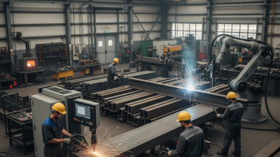
Steel fabrication turns drawings and raw plate into load-bearing components through cutting, forming, fitting, and welding. The final connection often depends on the welding process selected. MIG welding offers efficient deposition for clean, accessible joints. TIG welding provides precise control and a neat finish, especially on thinner sections. SMAW welding remains practical for outdoor work and difficult positions.

Under AWS D1.1 requirements, the procedure must match the steel grade, joint design, and service demands. Welders follow approved welding procedure specifications, including amperage, voltage, electrode type, preheat, and interpass temperature. Fit-up matters too. A small root gap can change penetration. Inspectors may use visual examination and additional testing when required. In real fabrication shops, experienced welders still find unexpected distortion or porosity. That is why measurement, cleaning, and documentation cannot be treated as minor tasks. I would not assume a strong-looking bead is automatically a qualified weld.

Tips: Clean mill scale, oil, and moisture before welding. Use the correct consumable and verify its storage condition. Keep parts aligned with clamps, but allow controlled movement during cooling. Record heat input when the procedure requires it. If a weld looks questionable, stop and investigate before adding another pass. A short delay is cheaper than rework.

Finishing and Inspecting Steelwork: Coatings, NDT, and ISO 3834 Quality Controls

Steel fabrication does not end when plates are cut, welded, and assembled. Finishing and inspection protect the structure long after it leaves the workshop. Surfaces are cleaned to remove mill scale, oil, weld spatter, and visible rust. A suitable coating system can then reduce corrosion caused by moisture, salt, or industrial chemicals. Dry film thickness should be measured at several points, not guessed from appearance.

Inspection also includes non-destructive testing, or NDT. Visual testing can reveal undercut, cracks, poor alignment, and incomplete finishing. Ultrasonic testing may detect internal weld flaws, while magnetic particle or dye penetrant testing can expose surface discontinuities. Each method has limits. A clean-looking weld can still contain hidden defects. That is why qualified personnel, calibrated equipment, and clear inspection records matter. ISO 3834 quality controls strengthen this process by defining welding responsibilities, procedures, personnel competence, and traceability. In practice, paperwork sometimes feels excessive, but missing records can weaken an otherwise sound fabrication job.

Tips: Match the inspection method to the weld type, material, and risk level. Check coating thickness after curing, especially around corners and weld toes. Keep photographs, test reports, repair details, and material certificates together. Do not treat rework as failure; it is useful evidence that the quality system is working. Still, repeated repairs may indicate poor fit-up, rushed welding, or an unsuitable procedure that deserves honest review.