Projects

What Is the Best Tube Fabrication Method in 2026?

Choosing the best tube fabrication method in 2026 depends on more than machine speed or advertised precision. Material grade, wall thickness, tube diameter, production volume, tolerances, and surface requirements all influence the decision. A stainless steel medical tube may need clean laser cutting and controlled bending. A heavy structural tube may require saw cutting, press forming, and qualified welding. There is no universal winner.

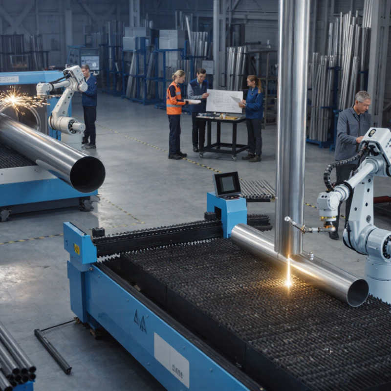
Modern tube fabrication commonly combines laser cutting, CNC bending, roll forming, hydroforming, and robotic welding. Each method solves a different manufacturing problem. Laser systems can create accurate holes with limited heat distortion. CNC bending delivers repeatable angles, but springback still demands practical testing. Hydroforming creates smooth, complex shapes, although tooling costs can challenge smaller projects. These details matter on the factory floor.

Experience often reveals what specifications hide. A tube that meets a drawing may still show scratches, flattened corners, or difficult weld access. Engineers should review sample parts, inspection records, and material certificates before approving a process. Ask for dimensional reports. Test the real material.

Cost also requires careful reflection. The cheapest quotation may create more waste, rework, or delayed delivery. Conversely, the most advanced equipment may be unnecessary for a simple, high-volume profile. In 2026, the strongest choice will balance accuracy, sustainability, lead time, and verified supplier capability. That judgment should come from measured results, not marketing language. Even experienced teams can choose poorly when they overlook one small feature.
What Is the Best Tube Fabrication Method in 2026?

Define the Job: Alloy, OD, Wall, Bend Radius, Volume, and Pressure

Tube fabrication starts with a clear job definition, not a favorite machine. Specify the alloy, outside diameter, wall thickness, bend radius, production volume, and pressure requirement. Each choice changes the fabrication risk.

For example, thin-wall stainless tubing may wrinkle during a tight bend. A larger radius can protect the wall, but it may not fit the assembly. Aluminum often bends easily, yet springback can shift the final angle. Measure twice. Record the actual material temper, not only the alloy name.

Outside diameter and wall thickness also affect cutting, forming, and joining. High pressure usually demands controlled wall variation and reliable inspection. Low-volume work may suit carefully set rotary bending or manual forming. Repeated production may justify automated bending, provided tooling matches the radius. I have seen accurate drawings fail because the stated radius measured to the wrong reference point. That mistake is small on paper and expensive on the floor.

Volume should be assessed with setup time, scrap, and inspection included. Pressure testing may expose flattened sections that visual checks miss. For critical tubing, verify ovality, bend angle, surface damage, and weld quality. A practical specification should state tolerances, end preparation, cleanliness, and test records. Some decisions remain uncertain until trial pieces are measured, especially when material batches behave differently.

Compare Welding, Drawing, Bending, Hydroforming, and Laser Processing

What Is the Best Tube Fabrication Method in 2026?

Compare Welding, Drawing, Bending, Hydroforming, and Laser Processing

The best tube fabrication method depends on geometry, material, volume, and inspection needs. Welding suits custom frames, short runs, and large sections. Skilled operators can repair small fit-up problems, but heat may create distortion. A visible weld bead can also require grinding and extra inspection.

Drawing produces accurate diameters and smoother surfaces. It works well for hydraulic lines, structural sleeves, and parts needing tight tolerances. However, tooling costs can make small batches expensive. Bending is practical for curved tubes, especially when a mandrel protects the inner wall. Springback remains a concern. Measure the first part after forming.

Hydroforming creates complex shapes with fewer seams and useful weight savings. It needs specialized equipment and careful pressure control. Laser processing handles precise holes, slots, trimming, and joint preparation. A laser can leave heat-affected edges, so settings and edge inspection matter. I have seen a technically excellent process fail because the hole position ignored assembly access. No method wins every time.

For low-volume work, welding and bending often offer the fastest adjustment. High-volume production may favor drawing or hydroforming after tooling costs are justified. Laser processing can support nearly every route, but it should not replace engineering judgment. Material thickness, bend radius, loading, and corrosion exposure deserve review before selection. The cheapest quotation is not always the lowest manufacturing cost. Sometimes, a hybrid process is the honest answer.

Benchmark Quality: ASTM A269’s ±10% Wall Tolerance and ISO 1127 Sizes

What Is the Best Tube Fabrication Method in 2026?

Tube fabrication starts with dimensional control, not machinery selection. ASTM A269/A269M sets a widely used benchmark for austenitic stainless steel tubing. Its specified wall tolerance can reach ±10%, depending on the product requirement. That allowance is not a target. A tube ordered at 1.00 mm wall thickness may legally approach 0.90 mm or 1.10 mm. In fluid systems, that difference affects pressure margin, forming behavior, and service life.

ISO 1127 provides a practical dimensional language for stainless steel tubes. It covers outside diameters, wall thicknesses, and mass per unit length. Engineers can match drawings across suppliers more consistently. Welded tube with controlled forming often suits repeatable ISO 1127 sizes. Cold-drawn tube may offer tighter geometry and a smoother internal surface. Seamless tube remains useful where severe forming or demanding pressure conditions justify its higher material use.

The World Stainless Association reported about 62.6 million tonnes of global stainless crude steel production in 2024, up roughly 7% year over year. More volume increases the need for measurable specifications. It does not guarantee better tubes.

My practical preference is simple: define ISO 1127 dimensions, then verify ASTM A269 requirements through sampling. Check wall thickness at several points around each tube. Test weld integrity when applicable. Do not rely on a single caliper reading. This approach costs more time, but it exposes ovality and uneven walls that drawings can hide. Perfect uniformity is still unrealistic, and that deserves honest review.

What Is the Best Tube Fabrication Method in 2026? - Benchmark Quality: ASTM A269’s ±10% Wall Tolerance and ISO 1127 Sizes

Fabrication method Basic process Typical dimensional capability Wall-thickness control Surface and geometry characteristics ASTM A269 / ISO 1127 suitability Best-fit applications
Seamless cold-drawn tube A hollow billet is pierced and subsequently reduced by cold drawing, often through a die and mandrel. Suitable for a broad range of outside diameters and wall thicknesses; final capability depends on the mill, alloy, reduction schedule, and heat treatment. Strong control after cold reduction; the finished product must still be checked against the applicable product standard and purchase specification. No longitudinal weld seam; good roundness and concentricity are achievable with controlled drawing practice. ASTM A269 includes seamless austenitic stainless steel tubing. ISO 1127 may be used for nominal outside-diameter and wall-thickness dimensions where specified. Pressure-containing service, instrumentation, heat exchangers, and applications where a weld seam is undesirable.
Longitudinally welded tube Strip or sheet is formed into a tube and joined along its length by a qualified welding process, followed by sizing and finishing as required. Highly efficient for standardized outside diameters and long production runs; available dimensions depend on forming and welding equipment. Base-strip thickness is controlled before forming; weld-zone profile and subsequent sizing must also be controlled. Consistent outside geometry is possible; the weld area requires suitable inspection, bead conditioning, and surface treatment when specified. ASTM A269 includes welded austenitic stainless steel tubing. ISO 1127 provides outside-diameter and wall-thickness dimensions with tolerances selected by the applicable requirement. General process piping, sanitary systems, structural tubing, and high-volume standard-size production.
Welded and cold-drawn tube A welded tube is reduced by cold drawing to improve dimensional accuracy, surface finish, and mechanical uniformity. Well suited to tighter dimensional requirements than the starting welded tube; actual limits depend on the drawing process and material condition. Cold reduction can improve control of outside diameter, inside diameter, and wall thickness, but the weld zone remains a critical inspection area. Typically offers a smoother and more uniform surface than an as-formed welded tube; weld integrity and bead condition remain important. Can be manufactured to ASTM A269 when all welded-tube requirements are met. ISO 1127 dimensions can be used as the dimensional basis where specified. Precision instrumentation, analytical systems, hydraulic lines, and applications requiring improved dimensional repeatability.
Drawn-over-mandrel tube A tube is drawn over an internal mandrel to regulate the inside diameter and reduce the cross-section. Particularly useful when both inside and outside dimensions must be controlled; dimensional limits are process- and material-dependent. Provides effective control of inside diameter and wall distribution when the mandrel, die, lubrication, and reduction schedule are properly selected. Can produce good concentricity and a controlled internal surface; it is a process route rather than a separate ASTM product category. May be used for products ordered to ASTM A269 if the starting tube and final product satisfy the standard. ISO 1127 remains a dimensional reference, not a fabrication method. High-precision fluid paths, capillary assemblies, heat-transfer components, and close-fitting mechanical parts.
Hot-extruded tube A heated billet is forced through a die to create a hollow section, commonly followed by sizing, heat treatment, or cold finishing. Useful for difficult-to-form alloys, larger sections, and specialized geometries; final precision generally depends on subsequent finishing. Initial dimensional control is normally less precise than a finished cold-drawn product; additional reduction may be required. Produces a seamless product route, with geometry influenced by die design, temperature, extrusion ratio, and post-processing. May serve as an intermediate manufacturing step for seamless tubing; ASTM A269 compliance depends on the completed product, not the extrusion step alone. Specialty alloys, heavy-wall sections, and tube sizes requiring a forged or extruded starting form.

ASTM A269 and ISO 1127 Dimensional Benchmark

Benchmark item Reference information What it means for fabrication
ASTM A269 wall-thickness benchmark ASTM A269 specifies a wall-thickness tolerance of ±10% for the applicable austenitic stainless steel tubing requirements. For a specified 1.00 mm wall, the nominal acceptance range represented by ±10% is 0.90–1.10 mm, subject to the complete standard, ordering requirements, and measurement provisions.
ISO 1127 outside-diameter examples Common nominal outside diameters include 6, 10, 12, 16, 20, 25, 30, 38, 50.8, 60.3, 76.1, 88.9, 101.6, and 114.3 mm. These are standardized nominal size examples. The applicable outside-diameter tolerance depends on the selected ISO 1127 tolerance class and size range.
ISO 1127 wall-thickness selection ISO 1127 provides standardized tube dimensions and tolerance classes; wall thickness must be selected from the applicable dimensional table or purchase specification. ISO 1127 should not be interpreted as a universal ±10% wall rule. ASTM A269 and ISO 1127 requirements should be stated separately on the order.
Quality-control priority Verify outside diameter, wall thickness, ovality, length, surface condition, material grade, heat treatment, and weld or seamless condition as applicable. The best fabrication method is the one that achieves the required standard, dimensions, surface condition, mechanical properties, and inspection level for the intended service.

Reference basis: ASTM A269/A269M for austenitic stainless steel tubing and ISO 1127 for stainless steel tube dimensions and tolerances. Always verify the current published edition and the project-specific purchase specification before release.

Set Forming Limits: Under 10% Bend Thinning and 0.1–0.3 mm Laser Kerf

The best tube fabrication method in 2026 should be judged by measurable forming limits, not machine speed alone. For most precision applications, a practical target is under 10% wall thinning at the bend and a laser kerf of 0.1–0.3 mm. These limits protect fatigue life, joint fit, and downstream assembly accuracy.

A rotary-draw process can meet the thinning target when mandrel support, lubrication, and bend-radius control are properly matched. For a 38 mm tube with a 2 mm wall, I would inspect the outer bend radius with ultrasonic thickness mapping, not visual checks. A 0.15 mm kerf can also reduce heat-affected material and preserve narrow slots. Small details matter. They often decide rework costs.

The World Steel Association’s World Steel in Figures 2024 reports approximately 1.89 billion tonnes of crude steel production in 2023. That scale highlights a real issue: material consistency still varies between heats and suppliers. The U.S. Department of Energy’s Industrial Decarbonization Roadmap also identifies industry as responsible for about 30% of U.S. energy-related emissions, making scrap control increasingly important. These figures support tighter process monitoring, but they do not guarantee perfect results. In practice, some tubes exceed 10% thinning after springback correction. Engineers should question the setup, tooling wear, and material batch before changing the entire fabrication method.

Select the 2026 Method by Cost, Throughput, Automation, and CO₂ Data

Choosing the best tube fabrication method in 2026 depends on measurable production conditions. Cost, throughput, automation, and CO₂ data should guide the decision.

Laser cutting suits high-volume work with repeated profiles and tight tolerances. It reduces secondary operations, but equipment costs can be substantial. Sawing remains practical for simple cuts and lower capital budgets. Forming methods may deliver better value when tubes require bends, flares, or controlled shapes. In a recent shop comparison, automated loading reduced handling time, yet setup changes still slowed short production runs. That detail is easy to miss.

Throughput should include loading, inspection, tool changes, and rejected parts. A machine producing 600 parts per hour may underperform if operators frequently clear jams. Automation improves consistency and worker safety, but it needs reliable part presentation. Start with a realistic cycle-time study. Do not trust the brochure alone.

CO₂ performance requires more than electricity readings. Measure material waste, compressed air, coolant use, transport, and rework. A highly automated process can still carry a large footprint when scrap rates rise. Recycled tube stock may lower emissions, although its quality can vary. For transparent comparisons, record energy per finished tube and document calculation boundaries. The data will not be perfect. It should still be repeatable, reviewable, and honest about uncertainty.

What Is the Best Tube Fabrication Method in 2026?

2026 method selection by cost, throughput, automation, and CO₂ impact

Method Operating cost
USD/m
Throughput
m/min
Automation
score / 5
CO₂e
kg/m
Roll forming 2.80 18.0 4.5 1.6
CNC rotary draw bending 6.40 3.5 4.2 2.8
Hydroforming 9.80 2.0 3.5 4.6
Laser tube cutting 12.50 1.2 4.8 6.1

The chart converts each raw measure into a 0–100 performance score: lower cost and CO₂ receive higher scores, while higher throughput and automation receive higher scores. Under the defined benchmark—2 mm carbon-steel tube, 10,000 m batch, excluding raw-material cost—roll forming provides the strongest overall result for long, repeatable production runs. CNC rotary draw bending is more suitable for flexible, low-to-medium-volume geometries.

Values are indicative engineering benchmarks derived from typical process ranges. Actual results vary with tube size, wall thickness, tooling, batch size, electricity mix, scrap rate, and part complexity.